
December 28th, 2015- February 12th, 2016: The Deprecated Dome
The first two months of this process was spent finishing the dome of BB-8. At the time, my plan was to create a static office decoration. With that approach in mind, I didn't give much thought to anything beyond 'make it look as awesome as possible.' This section shows the stages of printing/prepping/finishing my first BB-8 dome which ultimately ended up being way too heavy for the functional droid project this ended up becoming. Below you can see the log for the building of this dome
BULK PRINTING
Sphero BB-8 inspects the manufacturing of his big brother
You quickly find the urge to assemble irresistible
The lens of the radar eye is a filed down clear plastic Christmas ornament
Having printed all the parts and purchased all the supplies, the collection started to take up some pretty heavy real estate.
This is the Radar eye assembly. 4 pieces; The back panel, the internal structure, the housing and the lens.
It was at this point in the build I made a real effort to start documenting each stage. The pictures from here are more frequent and hopefully my explanations can be a little more helpful.
A theme you'll see in this build and most others are constant dry assemblies. Watching this droid come together is a lot of fun.
These are the 5 main pieces that make up the BB8-Builder's club dome. Each of these pieces is actually composed of several sub-pieces as you saw in the earlier print pictures, but after assembly you end up with; the Dome (left), The Skirt (middle), The Top (inside Skirt), The Dome Ring (right), and the Pie Panel (back).
Same parts assembled (bottom to top); Skirt, Ring, Dome, PIe Panel (the Top doesn't sit without glue)
With all the sub-pieces glued into their final configuration I can start prepping each piece for paint by filling gaps, sanding and priming.
Of course, just as I'm going to start priming we get the biggest snowstorm in history. Temperature has a huge affect on spray paint, but for the priming stage I didn't care much. I warmed the cans inside and let them dry in the cold however they dried. At this point it was more about seeing where the trouble spots were and where I need to sand/add more putty.
Rather than keep each piece at the same stage of the process, I started taking some pieces to the next level as I continued to work on the others. In practice, this basically meant I began finishing parts in order from smallest to largest.
The first of these parts was the holoprojector. This was also the first piece printed so it was nice to get this one squared away first.
Next up was the pie panel. A lot of builders are taking different approaches to this with regard to method and desired outcome. For me those are 'rub n' buff' and 'weathered aluminum' respectively. Rub n' buff is a finger applied finish which can be a little tricky to work with but delivers really impressive results.
The trick with Rub 'n Buff is to have the perfect amount on your finger when applying. Too much and it gets gloppy, too little and it gets splotchy like you see here.
I took two of my better segments and tried some texturing. I used some rough grit sand paper to make a bit of brushed look. You get a good look at some of the splotchiness left from poor application.
After getting all the panels looking as they should i applied a little more 'brushing' to the whole piece.
I used the same technique to add the silver to the dome ring.
I even went a little further with the Rub 'n Buff adding it to some of the prongs of the radar eye surround to give a little weathering to that area.
The biggest challenge was smoothing out the dome. Unlike some of the other pieces there was no room for negotiation here. Being the main focal point of the droid, this thing had to be SMOOTH. I think I went through 5 or 6 rounds of sand/prime/sand, but it ws totally worth it in the end.
The skirt will be the least visible piece of the head, but still requires some attention (obviously).
Last dry assembly before painting. The first goal is the whites but unfortuantely I didn't save any of those pictures for some reason. So on to the grey ring!
Here you can see my custom garage-paint-chamber. I borrowed every space heater i could and got the temperature up to about 60 degrees in February in New Jersey...not too shabby. My masking game was pretty on point too
....buuut just in case it wasn't I also had my custom shoe-box paint guard.
Here's the white/grey ring stage. All that's left from here is to apin in the oragea nd we're looking pretty BB-8
I used two types of type to mask it off. A Tamiya modelling tape for the actual edge, then some standard blue painters tape for the rest.
Pro tip: i masked this off for the orange, but before I sprayed orange i did two more coats of white. This was to fill any bubbles or gaps in the tape with white and ultimately seal thoes gaps for when you add in the color.
Orange sprayed on top.
For some reason these next couple images make it look like I sprayed a different orange on the top and bottom. I assure you I did not. The actual orange is most closer to the top.
A dry assembly and the Sphero looking on.
I do believe this is the last image of the Sphero. Soon after this my daughter got a hold of him and he was never seen again.
I bought a light kit from club member Steve Strong. It doesn't have any sounds programmed in, and I thought having the hardware and the board would give me the opportunity to program the sound into it myself. In the end, I used the Mega in here for the main body controls and tore the rest apart for parts anyway. For my final droid I am using something else for lights/sounds
The light kit test.
February - June 2016
As with the deprecated dome, I had an issue with some un-used body panels. This one isn't quite as linear as the dome because I worked on it in parallel with the internal drive mechanism. For the sake of organization over chronology, I moved all the pictures of these body parts to this next section. So bear with my Tarantino-ing here.
This is the terminology I agree to try to stick to during the discussion of the body
During the printing of these body pieces I learned the true meaning of changing filament on the fly. A ton of these prints had filament rolls changed throughout and even had color changes as i ran out of certain colors.
Here is the collection of ring and triangle pieces that will ultimately not be used. I'm probably going to put them on the Jakku junkyard one of these days for those in the club that may be interested in some parts.
Grouped together
Using the wheel to glue the triangles on a proper curve.
Getting the rings glued together.
Sanding down the edges
Guide filament
Unassembled Ring
All glued.
February 12th, 2016
So why all these useless parts? As I mentioned earlier, there was a point in the build when I knew I would not be satisfied putting in all these hours for a simple decoration. After seeing some successful approaches to drive mechanisms I decided to give a functional droid a shot. James Bruton of XRobots' V3 design was the one that appealed to me most. Due to some initial size changes and being hindered by a smaller printer, I started recreating the file in 3D Studio Max so I can export print files and change things on demand to test ideas/accommodate the parts I bought which would ultimately be different than the parts XRobot's used his build.
Right off the bat there were some thing I wanted to alter from the XRobots build. At this point I was still planning to use the club body parts which had an interior diameter of 506mm. XRobot's diameter was 500mm, so I needed to beef up the sides by 3mm all around. I started with the full 'cheese wheel'
If I take the 360 degrees of the outer wall and divide it into 20 individual pieces representing 18 degrees each I end up with something like this.
The holes on the sidewalls will be matched on an internal rim for stability while assembling. After everything is assembled, the 20 cheese pieces and the inner rims will all be solvent welded together to form a solid wheel weighing roughly 10 lbs and smooth enough to roll around. At that point I can remove all the screws as it will essentially be one solid hunk-o-plastic. It will eventually be covered by my Body Skins so it doesn't have to be 100% perfect.
Printing on a Makerbot Replicator 2x meant I had to split up each cheese into 2 parts. I went with a double dove tail so I had more alignment checks built in.
EPIC FAIL! This was my first print. I did a test of a single piece and good thing I only did a single. Turns out, after printing PLA for a month, the build plate had developed a nice 1/8" layer of glue-stick glue on it (which I had used to make the PLA filament stick to the bed a little better). The ABS I started printing with didn't like that and popped off the bed mid print. Oh well, all that print-spaghetti will help make some fine ABS Slurry
After a little printer calibration and we were off to the races. James at XRobots said he was printing each slice in about 4 hours...these were taking 11 hours each on my MakerBot. Not surprising being this printer was 'cutting edge' about 4 years ago. Also they are 100% infill an 3mm thicker than XRobots', so that doesn't help print time.
Here's a quick study on the individual cheese slices. They aren't exactly identical even though they look like it. A more symmetrical slice could probably have been made to keep it as one modular piece, but ultimately it would have been extra effort for little payoff.
I was able to keep the collection of each of the two pieces straight by branding them in software. I had my "circles" and my "triangles."
Fitting went surprisingly well.
I had to cut the internal rim into fifths instead of fourths once again due to the size of my printer.
February 14th, 2016
At this point the printer was really just on autopilot with minimal input from me.
And bonus! that part from the 'spaghetti' picture above? I salvaged it. When I looked at the piece I realized it was nearly 80% completed when it failed. That's like 4 hours of printing at least, so I measured it and created a new section to print and solvent welded on. It worked really well. You may be looking at it saying "That looks like shit," and you'd be right, but knowing the amount of slurry and sanding this wheel is going to go through, combined with the fact that this wheel will never actually be seen on the final product means it's a wild success. When the wheel is slurried and sanded I wouldn't be surprised if you had a hard time picking out this particular slab.
February 16th, 2016
I think at this point I have enough pieces to start assembling.
For now it's all screws. Each half-slab warped and cooled in it's own way so finding an order of slabs that left as little of gaps as possible was a challenge. All and all things fit really well.
February 17th, 2016
Trying to see the big picture of how it is going to look when it's complete. Waiting 11 hours at a time for one slab is no fun at all. However, at this point I'm well over halfway and if all goes to plan it should only be a few more days of non-stop printing.
Well of course, everything is not going to plan. My printer kicked it this morning. Needs to get some parts replaced to get'er up and running again. On a temporary hold for this part of the project. This is as far as I got before she went.
February 22nd, 2016
With the Makerbot down, I called makersupport and got the impression "best case scenario" would be a few weeks. I had been eyeing up the Taz5 anyway, so this hiccup ended up being the final push I needed to make the purchase. Amazon Prime had it to my door in 2 days.
This will be the new setup when the Makerbot is fixed. Until then it's time to break in this Taz.
Here's a quick video of the Taz5 printing one of the cheese slabs in one piece. It's pretty crazy fast. I got the remaining slab pieces to print in 3 hours and 38 minutes! Down from 10 hours 58 minutes. That's a pretty impressive difference.
First full-size slab off the bed. I'm using some "quick and dirty" render settings to bulk print these slabs as fast ass possible. Fast printing and huge layer heights.
If you're printing long parts and wont have the luxury of not caring how it actually looks in the end, you might want to look into getting an Uninterrupted Power Supply (UPS). For some reason the power has been 'fluttering' in my house over the past couple weeks. I lost a couple of prints in the process. [For the cynics out there, "No" it was not the printing that caused the power fluctuation. In fact, that part of my office is on a separate circuit that was unaffected. The computer on my main wall controlling the print wasn't so lucky). This this cost about $140 bucks on Amazon and gives some good piece of mind to know all my computers/drives are safe from power outage. Even if my house completely loses power this little guy will give me enough time to safely shut everything down.
Here was my "power outage" print. I measured the resulting piece and hacked that portion off of a second print. Now I can solvent weld them together. Like I said, it's a great solution if you're not too concerned with final appearances or if plan on doing finish work anyway.
Clamps are good.
February 25th, 2016
The last piece came off the printer today! I threw everything together to get an idea of the height (Not including antennaes it will be about 15mm taller than this).
SANDING: I made a big jar of thick ABS slurry and a big jar of thin ABS slurry and began solvent welding all of the planks and the rims together. It was pretty amazing how much slurry this thing soaked up into it's gaps. I did a few rounds of the outside and inside to get it really sealed and holding tight.
After it was dried a bit I made the daring move of taking all the screws out and letting it stand as the giant single piece of plastic it now kind of is. I sanded it really well on the outside and inside which exposed soem more gaps that didn't get hit in the first round, so I did another few coats of thick and thin slurry to really get everything welded together.
Looks like I won't be needing to push BB-8 anymore! The motors that will eventually drive and tilt BB-8 arrived today. They are the windshield wiper motors out of a 97 Dodge Ram!
The trick to getting a super-smooth roll is a super-smooth inside. I lathered on some ABS slurry to fill low the spots inside the ball and began sanding to reduce all the high spots.
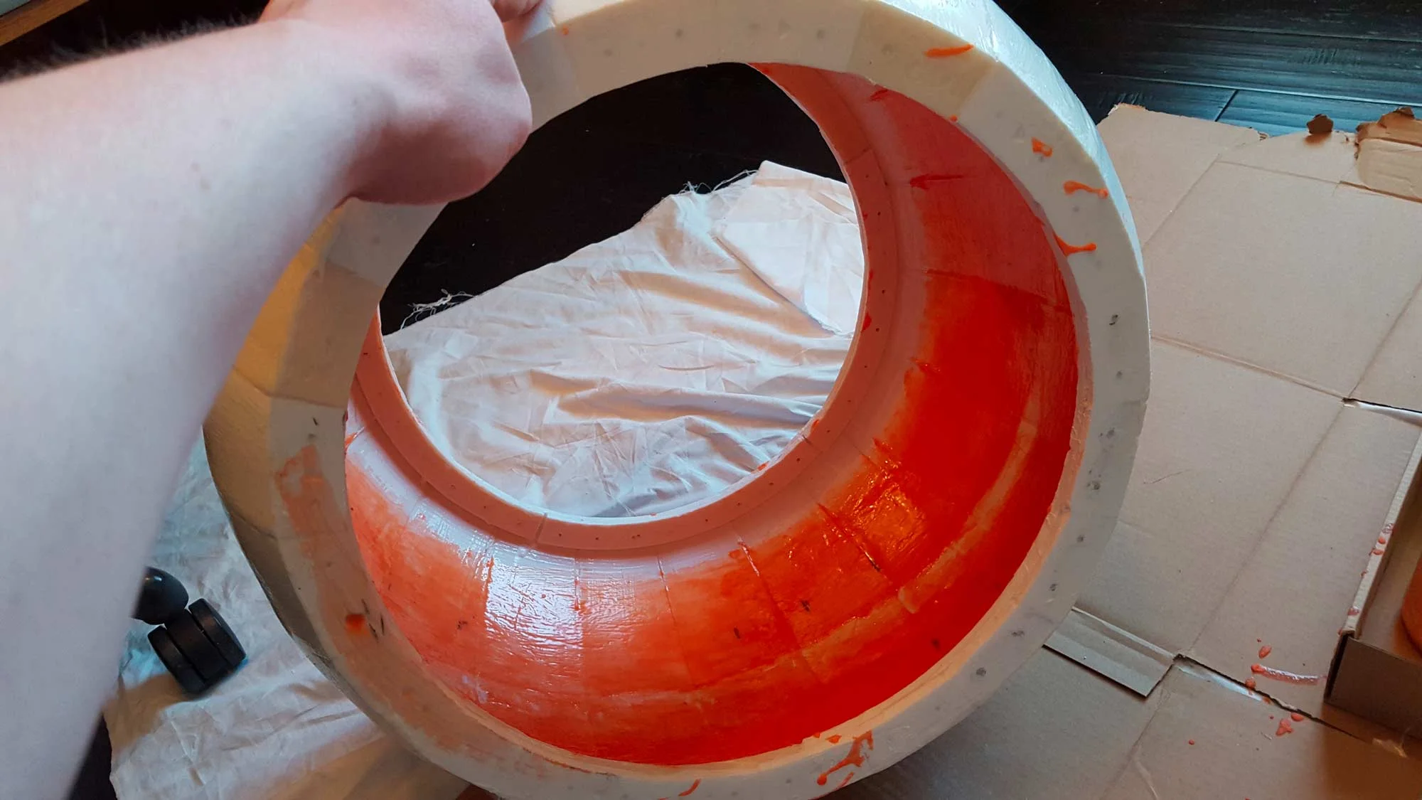
I made little black marks where the carriage of the internal drive mechanism will be so I can focus on sanding 3 smooth tracks instead of having to do the whole thing.
I also printed some internal rim covers. When I assembled everything it left some serious gaps. Since there will be wheels running on this rim I wanted it to be as smooth as possible.
Quite a few hours of sanding later and this thing was SMOOTH!.
LIke...really smooth.
March 18th, 2016
Now that the ball was prepped for the internal drive mechanism it's time to start building! The logical thing would be to start with the carriage or 'banana,' but after watching the video of James (XRobots) building the flywheel I knew my excitement would force me to start there.
With the Taz5 fully operational, I'm now able to print full size pieces. This is a huge help. Here are the 3 pieces that will come together to form the flywheel.
The Taz5 comes equipped with a thin sheet of PEI plastic on the print bed. This is advertised to be "very easy to adhere to" when hot and "easy to pop off" when cold. They weren't kidding. I tried removing a piece while ti was still warmish and it took some of the bed with it. That was a 40 dollar lesson learned the hard way.
Screwed/solvent welded the 3 pieces together to form the flywheel.
I filled the flywheel with roughly 15 pounds of lead. This will aca swinging/spinning mass to help make BB-8 maneuverable.
Back to a more logical build timeline I started printing all the parts for the "banana" structure.
Banana Parts piling up.
Finding time to assemble was tough with my work schedule and it got the point where I decided I'd just wait until everything was printed and make a little timelapse video of the whole thing. So there's that to look forward to.
Printed the motor mount to the main drive wheel
In addition to buying the new printer, I bought an extra extruder nozzle for it called a Flexystruder. This allow you to print in flexible material (I use Ninjaflex). This is the material I will be using for all wheels/tires for the build. Just like with plastic builds you have control over the density of the piece, so you can print rubber as thick as a hockey puck or as squishy as a whatever. Most of the wheels for this build will be printed with a density of 90% or greater, except for the spked wheel coming up for the flywheel control.
As you can see in that last pic, the printed recess for the tire doesn't align due to having to MASH that tire onto the motor much further than I thought I would have to. Oh well, nothing a little dremel won't fix.
This print I am super proud of and have to give myself a little pat on the back. I printed the "trousers" which have a recess for a bearing that will go around main axis. As soon as the print finished I test fitted the bearings and thankfully they fit. Then the genius part....I decided to leave the bearings in the hot print on the bed. As the plastic cooled it contracted around the bearing and the bearings basically installed themselves. Those suckers are in there for good with no glue or anything.
I also took some pics of the assembly process as i went through.
Isn't it great when your plans work out perfectly! (Note: This blog doesn't show the countless breakdowns and reassemblies and reprints and bloody fingers and tears and frustration and ultimate questioning of ones own purpose/intelligence)
At some point I decided to redesign the axis holders. I wanted to add a recess to the back for a washer and give the axis a bit more to hold on to. The axis, by the way, is just a piece of electrical conduit bought at lowes and sawed to length. No pics/vids of that fiasco, sorry.
I closed off the ends leaving only the hole for the internal studding. This way a washer can fit in that recess with a nut on the end and not scrap on the wheel.
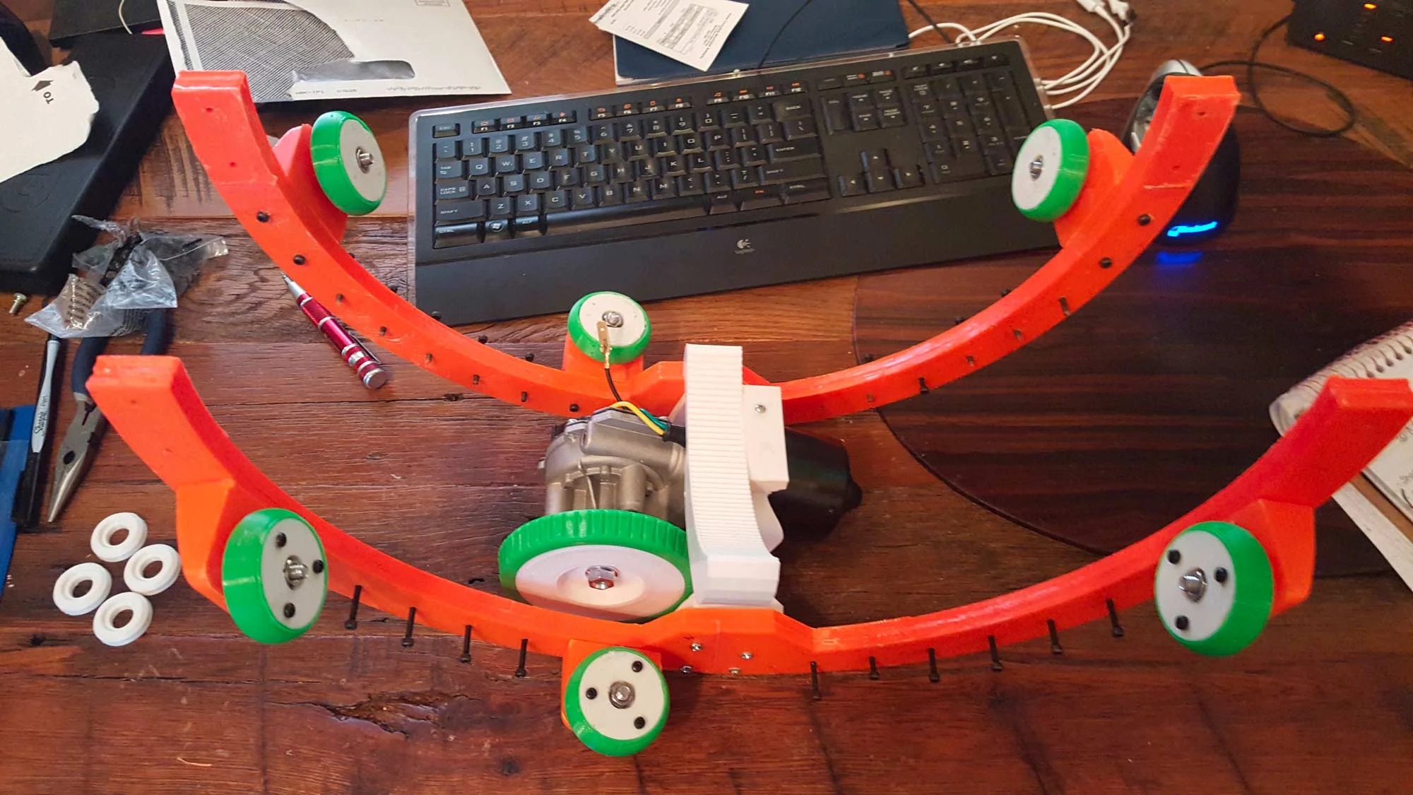
Basic Banana assembly ready for it's first installation.
I put the trousers on and put it for a test in the ball to run the motor. The power supply sucked so all I got was a little stutter from the motor, but I'm going to order some Li-Pos and do it up real deal style soon.
Next I added the flywheel on and put the whole dang done thing together.
This pic above shows my "part graveyard" from just this week. I think the overall takeaway from this project with regard to 3D printing is going to be "just because it works in CAD doesn't mean it's going to work in real life." I have a lot to learn about tolerances, printing thresholds, and fittings. The main motor mount is driving me up a wall right now. Or actually, it's not driving anything because I can't print it properly. The original one was printed in two "odd shape" pieces and my overzealous self didn't take enough care when attaching them and the curved rack had a bit of a tilt to it. Normally I'd let it slide but since this assembly is arguably the most important part of the drive, I had to be a bit picky. My second iteration was not well-thought through and now sits next to the original. Version 3 of the motor mount is just an "idiot-proof" version of the first iteration, so hopefully I'm not THAT much of an idiot. The other parts had various fitting issues.
March 18th, 2016
And look what just arrived as I was compiling the video!You know those batteries that they don't let you ship or take on a plane because they could explode and cause a massive fire.Well I thought it might be a good idea to stuff a shit ton of them into my first robot build!Woohoo!
With the batteries in hand I can wire up the motor for the first motorized roll test.
In the video above, the wheel was spinning just fine, just not getting any traction on the inside of the ball. So I had to print a bigger tire.I want the tire to be as small as possible while still working, so I printed a large one, which worked.Then I printed a medium one to see if I could get away with that, but it was still too small.So I put the big guy back on and we're ready to rock.
And that little show initiated a new fan into the bb8 universe
With the bottom "drive" portion of the internal mechanism scquared away it's time to focus on the top "head" portion.
This will be the what attached the head the control arm to the Y-axis. This is going to be a bit of a gimbal, with rotation along the X and Y axis for the arm. You can see a recess on either side for a bearing.
This is the head control arm which will attach to the last piece and ultimately hold the magnetic coupling which will pair to the head. It will rotate around the X and Y axis with the previous part and have a spindle running up the middle which will rotate around the Z axis. So all in all there will be 3-axis control over the head and body. That should be fun.
For some reason I really love inserting bearings into perfectly printed recesses.
This is the assembly that holds the servos that will control the head of BB8
When my work schedule gets out of control the only thing I can do is print. I had a couple crazy weeks which resulted in a huge pile of parts waiting for assembly.
March 21st, 2016
Next up is the top of the head control arm, the Body Magnetic Mount (BMM)(no not poop). This is anohter instance where my build will differ drastically from XRobots' . I'm planning on making a heavier head than James did thus I need more magnet power. I began designing a different configuration.
Here are the iterations of the BMM, most never made it out of software.
Look who's back! Mr. Makerbot up and running and printing my BMM.
The configuration I landed on was a large 2 inch magnet in the center and four 1 inch magnets arranged around it . This presents the problem of not being able to have the studding run all the way through the BMM and required a little planning for installation.
Next up is the other side of the magnetic coupling, the DMM. I'm using a small lazy susan bearing in the head to keep all the mechanics as low down as possible. So I first printed a test piece to make sure everything lined up.
The test was pretty successful. Ultimately those raised cone shapes you see will be printed as separate Ninjaflex spacers. I will print them in two densities in case I need them to "squish" more to allow for more clearance. The holes in this were too big so I shrunk them and then prined it in a higher density infill to deal with the magnetic stress it's going to be under....I just hope it holds together.
Here is that same DMM piece with the NinjaFlex bushings attached. I printed it at about 70% density and 20% density. If there is too much friction I can always just put the 20s on and squeeze them real tight or just remove the bushings all together and give the magnets a bit more clearance off of the BMM mags.
In addition to needing more magnetic pull, the heavier head will require a bit more counter-weight. Adding static mass to the bottom of the ball will keep the top-heavy droid from falling out of control. I had a bit of lead left over from my flywheel fill, so I decided to create some weight containers that would attach to the banana.
Orange saddlebags getting test filled and weighed.
This is actually the smaller of the two SBs and I got over 2 pounds in! The saddlebags aren't even due to the offset motor configuration.
Printing the wheels for the head and the larger internal wheels to accommodate the the extra saddlebag weight.
Stripped down banana ready for new wheels and saddlebags.
Pretty good fit.Hard to tell in this pic of black on black but the saddlebags hug that motor really well .
Double checking that the bottoms of the exterior bags don't scrape the ball.
All filled up and ABS Slurried into place. Over 5 pounds! That should help a lot.
Fitted.
My goal at this point is to make this next installation to the ball the last one. Getting all this stuff in and out is tricky and stressful. Once everything is "in there, in there" I can start adding the top half parts and wiring. I'm trying to think of any parts I can add on now which won't hinder the installation but will save me time on having to install 'into' the ball.
The lowest hanging fruit in that department is the potentiometer. This will measure the degree of rotation of the flywheel assembly (Yaxis). I have no desire to try to install/wire/solder this insdie the ball.
There you have it folks, the first official piece of wiring for BB-8.
Ready to complete the flywheel assembly for (hopefully) the last time.
Flywheel assembly ready for life on the inside.
Checking the fit of the batteries.
Uh oh......
I solved my wiggly motor problem and made the ball a lot smoother but didn't correct the tilted axis part at all. That was due to all the weight in my saddle bags being towards the back of the ball. So before I can go further I have to balance this out. I know it can be done with the inertial measurement unit (IMU) and stabilization through software, but why not at least try to start with a balanced droid? One problem, though, I'm out of lead shot.
I printed the first bit of stabilization and bought some steel shot from craigslist. I quickly learned one thing. Steel shot weighs no where near as much as lead shot. Like, not even close. As such this didn't do much to balance it.
So I quckly printed more parts and really loaded up that front side with mass to balance it out. As expected, I overshot, and now the front side was too heavy.
I decided the best bet was to take the weight out of the highest point, to keep the added mass as much above the main wheel as possible. After I did that I had a lot of extra room in my little 'bananhanger' so I decided to build another one for the other side so I can add balanced weight in the future if I needed to.
And when all is put back in the ball we have a pretty fairly balanced droid. Anything less than perfect will be fixed with the software.
With everything back in the droid, everything staying un-wobbled, and everything balanced, I'm ready to move onto the rest of the installation.
Here's our goal.
First thing is I got that Potentiometer installed. The mechanism fit pretty well (but later will go on to get in the way of my guide wheel assembly, which I will have to reprint).
Next up was getting the servo horns in there. This was the real challenge of the day. There is little to no room on the outer ends of the inside of the ball.
In there! That might prove to the most physically difficult part of the installation.
Next up is getting the Head control Arm assembly installed.
All main mechanics installed!You can still see a little floppy guide wheel assembly on the left there.That needs to be reprinted.I also have some electronics mounts that need to be installed and some that need to be reprinted, but overall, this is just about all 3D printed parts for the inside of the ball!
Here's the real star of the show.
Now that all the mechanics are in, I can start on some of the electronics. The first thing I need to do is pair my two bluetooth modules. Then get the remote controller transmitting data over that bluetooth. Then get the ball all wired up and receiving that data.
April 24th, 2016
I'm a little late catching up on the blog, but that's only because I usually update the blog when I hit a roadblock...and generally speaking that hasn't happened lately. I did have a pretty busy work week last week that kept me away from droid progress, but I more than made up for it this weekend.
First, I got the bluetooh modules paired so the remote control can talk to the droid. Not much I can post to "show" that, but suffice it to say it works and has been tested again and again, were good.
Now let's get the hand set taken care of.
First I need to setup the arduino that will be controlling the Handset. The smallest one on the market is the Arudino Pro mini. Like, super small. Like .7" x 1.3."
Just to give you an idea
All pins soldered into place
Here is the basic Handset frame directly from XRobots. Zero modification. I plan to re-do this later when I have a better idea of what I want out of a controller.
Wired the power in
Wired all the ground pins with some extenders to the top of the handset.
Copper wire that bridges those two wires across all the switch ground pins.
Joystick Logics
Switch logics.
USB power cable
Attach everything (including the bluetooth module) to the arduino.
"Light is green, trap is clean" All working!
I tested everything out with some code printing to the Serial Monitor of my Arduino and we're all good. Handset controls talking to Arduino Pro Mini Talking to Bluetooth talking to other bluetooth talking to Arduino Mega (cchhhaaaaiiiinnnnn keep us together [RUNIN THE SHADOWS])
Next up is to mount all the electronics into the droid. But before I can do that I have one small piece of maintenance that needs to be done. In part 9 of James's series he noticed a "fundamental mechanical flaw" in the design. Long story short it can be corrected with a set of guide wheels running higher on the potentiometer side. I installed those before I congested everything with the electronics mounts.
These will hopefully prevent the whole banana structure from lifting the main drive wheel off when pushed up a bit from inertia/magnets.
With that done I can mount my electronics.
This is the "Series" side of the droid. Easily Identified by no Arduino. The batteries on this side will be wired in series to give 24 volts which will power all of the motors
This is the Arduino or "parallel" side. I tend to use these terms interchangeably when speaking so I probably will while I'm typing this out as well. These batteries will be wired in parallel to give double the capacity at 12volts. This will power the the arduino, the motor controllers, and the servos for the head rotation and movement.
I made some custom wiring harnesses for the series and parallel connections. I have blade fuses coming out of each battery connection to hopefully stop any human-error turning into fried droid parts.
Series connection wired and reading at 23 volts (batteries need charging).
Parallel side wired and reading at 11.5volts. (Batteries here also need charging).
This is always the most frequently asked parts list, so here we go:
Amazon Link to Arduino Mega
Amazon Link to Motor Controller
Amazon Link to Inertial Measurement Unit (IMU)
Despite my best efforts, I fried two motor controllers. There is nothing more humbling then flicking a switch, hearing a pop, and watching that smelly puff of smoke rise in the air. Bye bye money, hello amazon delivery man.
April 28th, 2016
There is a lot of repetition in the next 4 videos. I was making them and posting them for various audiences (friends who kind of get what I'm doing, my facebook friends who don't know what I'm doing, and the BB-8 club who know even better than I do what I'm doing) so rather than try to decide which video was best I just posted everything I had from that week. The videos show a progression from getting the side to side stabilization working to driving it front to back for the first time.
It was about this time in the build when I realized my current finished dome was going to be significantly too heavy. I had the idea to print a 96% scale head which could be printed in one piece on my Lulzbot Taz5. I printed in a practically no-infill density with 3 perimeters. The weight difference was substantial.
96% Scale head coming off the printer.
I also reprinted my original casters much lighter.
96% head sitting atop the droid. I lso printed a one piece skirt/ring/interal structure combo to support the wheels and magnetic coupling.
It wasn't until I put the original full-scale head on that I realized how significant a 4% volume reduction would be....oops. Well at least now I have a test head.
After printing out the skirt/ring combo I soon realized my DMM was too big to clear the wheels. This is mostly due to the 2" magnet in the middle. I replaced it with a 1 inch magnet and reprinted a new BMM/DMM.
First head test! Obviously didn't go very well, but that was to kind of be expected. I was only using 3 magnets on the top instead of the full 5. Also, there was no head stick stabilization and I wasn't doing much to correct that on the driver end.
Flywheel rotation motors are in. I'll get these installed before the next test to allow me to spin the whole droid on the spot.
A little better than the first test. Nothing amazing. It's all about controlling the stick smoothing and aggressiveness. But at least the flywheel is working
More progress but I think I really identified the problem within the video when I noticed the wheels were hitting the side of the skirt. Also the body stabilization had to be tweaked to match the new head weight.
To address that problem inside the ball at the end of the last video I decided to add some height to the horns
I ultimately did a reprint of the horns with that spacer incorporated into the design, but I forgot to take a picture of it.
And ultimately I ditched the bottom portion of that test head to get rid of the wheel crashing issues. I have had some more success in making it stable.
I made this weight to place in the head. It's a bit overkill, but it will help give me an idea of the effects of too much weight in the head.
June 4th, 2016
Generally speaking, I'm happy with the locomotion. Time to start focusing on the body skins/panels. First I have to tackle the issue of how I am going to attach them. One thing I can't stress enough is how awesome/important it is to find someone in the club who is building a droid similar to yours and bounce ideas off of. For me, that person was Ian Martin over at Dejarik Creations. We were both pretty much building the droid in the same way, the only difference was after finishing the cheese wheel, I focused first on the inside on the ball and he focused first on the outside of the ball. This worked out great as we both had someone on the other side who had already tackled some problems. This was most prevalent in the case of the external frame. Ian NAILED it. It was perfect. I just had to modify it to fit my larger cheese and it was printing the same day.
Mirrored Frame ready for installation
Installed
The trick with these single axis drives is to offset the panels so you can't really tell it's a single axis drive. I created this animation to show how the panel rotation will look with Ian's frame..
This was my first real real good test. I feel like this thing is finally starting to drive like it should.
Now it's time to start focusing on the body panels. For the triangles I am reprinting them as Cary triangles with the built in hole for mounting. There are holes in the frame to align with these.
All 24 pieces for the triangles.
Assembly underway.
It's pretty amazing how well these things go together.
All 8 triangles.
Full Frame install. I also beefed up the reinforcments on the frame with some more slurry.
Test fitting first triangle.
Time to assemble the panels that I have put off for so long.
After the last driving test I beefed up my 3 prong head mount to a 4 prong. I think it will give it a bit more stability.
Instead of screwing straight into the plastic and live in constant fear of stripping the holes. I decided to install some threaded inserts.
A little tricky to get the right hole sizing but a precision drill bit really made this much easier. The inserts are embedded and working great.
On the triangle side, I was noticing the profile of the screw was starting to wear away the plastic on the inside. So I bought some PERFECTLY sized washers to fit in the holes.
Washer just bbarrely fitting.
Forced into place with the screw
This next bit probably wasn't necessary, but ultimately I think it will make for a better droid. My ring/panel assembles were not good...at all. There were crazy gaps, small gaps, all kinds of gaps which lead to inconsistent mistakes. I had time to play with so i decided to redesign the rings/panels as one piece with the Cary style hole in them so I can also mount the panels.
Pulled the ring into max and booleaned the same hole as the triangles. Then attached the panel. I split the whole assembly in half and printed each panel/ring assembly in two pieces .
All printed.
First panel glued together. This method isn't without it's own set of problems, but I like the idea of one giant seam instead of what I was dealing with. Plus now I can mount them.
This next bit was the second scariest part of the build (the first being powering up the motors for the first time before I knew everything worked). I'm going to be drilling straight into the cheese to embed the inserts.
First hole drilled.
This was much more painless than I originally thought.
Doing first 'for real' test fits.
Some spots fit better than others. There's going to be some serious adjustments made.
Still can't resist the mockups!
My quality control manager giving it the "slap slap slap" test.
All panels installed in a rough installation. Lots of gaps to fill and sanding of panels to be done.
Other Side.
Full mockup with old head. Starting to look like BB-8
Now on to the shimming
This the first of my large shims to fill the gaps between the panels.
Shim installed.
On the side you can see some of my smaller thinner shims that are cut to length as I go.
All shims installed on this horroshow of a panel. Sanding next.
Same Panel reinstalled.
lightly blurry but here you can see how the shims are making nice lines between the panels.
Panels off, batteries out. Time to get prepped.
First round of primer on the triangles.
Ready for round one of sanding. I'm going to do 150, 220, 300, 400 and see where that gets me. I'm going to mix in some of the putty seen here to fill up the larger gaps
Time to give the backs of the panels a little love.
Working both sets of panels over and over again getting them to a point where I can do a "final fitting."
The panels are all on and fitting well. The gaps aren't too bad and weathering will hide a bit of the hairier ones, overall the ball is real smooth. I'm ready for paint to start on the panels (triangles need some work still). But first I am going to do some testing on my internal dome mechanism (see next section).
Found a useful little trick for sanding.
Got the white laid down on the panels!
While I was waiting for that white to fully cure I painted the triangles and some screws
I began masking off for the silver. The yellow tape is a 6mm Tamiya masking tape which I really cant recommend enough. The small size lets you really get i there for the details and holds really well. The blue is just standard painters tape to cover off the big sections.
Ready for Silver.
Silver all set time to mask off for the orange.
I used the same technique here. Using the Tamiya tape on the details then covering everything with blue tape and cutting it out.
All panels done!
ASSEMBLY TIME! I can't even begin to tell you how much I have been waiting for this.
Assembly went really well. Getting very excited!
Below is a scrolling gallery of the weathering process.


And the final weathered body.
Next up for the body is clearcoating the panels and wiring up the body LEDs. I think I can do both at the same time as I disassemble the droid. I decided to go with neopixels for the body so I can create or not create animation cycles for the body panels. I did a quick print of a section of panel one and wired up my first sets of neopixels.
NeoPixel animation test
Practicing some NeoPixel wiring.
After all the testing fun it's time to get rolling on this thing. The arduino powering all of these neopixels is going to be mounted on the back of Panel 2. I downloaded a printable case for the Arduino Uno from thingiverse and glued it into place. Panel 2 seems like a good place to start my NeoPixel installation.
Arduino case glued to the back of Panel two.
I also began prototyping the LED windows to fit my panels and house the NeoPixels.
Got my first panel lit up. I was worried about bleed and light coming out where it shouldn't....so far so good!
Here's the back of the same panel. After feeling the weight I immediately rethought using the UNO. I'm going to put a nano in there instead.
I recently got kicked out of my current office to make room for our pending baby! Looks like my wife will be creating a full working human in less time than it will take me to make a droid. Anyway, it's to the basement with me! Here's my new setup!
Got my first few panels strung together with some alligator clips to test my wiring.
Ive begun marking where I'm going to need to route into the wheel to make room for these neopixels.
As far as routing the wires around the ball, I'm going to keep all wires along the orange perimeter of the frame. It has to cross over the top once to get to the other side, so there will be one very long route across. These little guys are printed in ABS to stick onto the frame.
With these installed on both sides I can now freely route wires without worry of interference from the mechanics.
As far as connecting everything, I need the connections to be removable many times, so I'm using some JST connectors. All the panels will be female (nature finds a way) and all the connections to the ball will be male.
Here is my first route. This will work.
Panel 2--> JST Connector--->Panel 6. Lights on!
This was the last panel I wired up. My solder game is on point!
Now that i know the lights all work, I took the frames off again so I can start routing the cheese wheel for the neopixels. I need to make room for the lights and wires so the panels can still lay flat. While I have the sides off I'm going to make 2 major upgrades as well. (More on that later).
Here is the recess for the wires and lights of Panel 4
Here is the recess for the lights and wires of Panel 3
Now that the lights on the body were taken care of, I was 'technically' ready to seal this ball up and focus on the head. A few things held me back (1) I'm not confident the magents would hold the head on in their current configuration. (2) The main drive wheel slips WAY more than I'm happy with. (3) My remote control needs to be rebuilt to add in the functionality of the head. I got to talking with another builder about using the R2 SHADOW system on the BB8. I spent a month or two trying to implement that and get it all set up , but ultimately it just wasn't working for me. The advantages didn't seem to outweigh the problems I was running in to. So I abandoned that. That leaves me with my original 3 problems to solve.
The first thing I did was take out my old head control arm. I needed to reconfigure the magnets.
I decided on my "bearclaw" design in order to get that 2" magnet into the mix. I made a spreadsheet on magnet decay and the 2" kept more of it's attraction over a greater distance. So while only twice as big, at 16mm apart the 2" magnets are actually about 13x stronger than the 1" magnets.
Here's the final ready to go back into the body.
Next up was the wheel slippage. I needed something else for the wheels to grab onto, nothing substantial, just something. I printed out these 1mm toothed tracks and glued them in. They'll probably need to be replaced from time to time as they die out, but it's not a ton of work.
The first test drive with these installeed was like night and day. Hopefully they last a bit of time.
Lastly i built a new controller! It controls the head and the body and even has the integrated switch for the 12v power on/off. It's a great controller!
I made a a little slideshow of the build. I even have some assebmly video shot if anyone really cares to see that.


The Final Dome
Since I started this blog with the "deprecated dome" section I should end it with the final dome as that's the last thing that will be complete. I'm going to start working on it while I'm still prepping the panels but will keep this section separate and last for clarity sake. I never really stopped working on the dome from the get go. I've done several iterations with different mounting systems, different skirt/ring combos, etc etc. As of this posting I think i have printed my final dome section, which is saying something. I'm about 80% sure I've printed my last skirt/ring combo and even less certain I've printed my last pie/top combo. Whats the reason for so many iterations? WEIGHT. I'm trying to find the best way to trim weight off this thing while still having it look good. My goal is 3.25lbs for the entire dome including lights and sounds. I think it's possible.
Here you can see my current dome collection. The one on the far left is my first /completed dome. The one on the far right is what will likely become int he final dome.
The first thing I want to update is my magnet mount/wheel spindle. Functionally, it's pretty good, minus one problem I will address shortly, but it's way too heavy and clunky. I have an idea for a much lighter sleeker version which will be functionally the same. In addition to this, I think I can shave some weight off of the casters in both the hub and wheel itself.
This is what I came up with. The image shows two wheels on one arm, but that's just so i can see it at both it's extremes. The central hub would be a separate piece that accepts the arms via a dovetail-ish joint. I wanted to keep it modular so i could use the same arms for a 4-armed version. I plan to use one of my spare domes as a perfect replica test head, so I'm building everything out in twos. Ultimately I will print 4 hubs (2 x 3 arms, and 2 x 4 arms) with an appropriate number of arms (8).
Printing with a light infill. 12% with 3 perimeters.
I also managed to print out all my wheel hubs and new tires. The problem I mentioned above with the old version was the axles in this assembly. They were 4mm steel which (1) heavy, (2) attracted to the magnets which lead to a ton of problems. So I went with 3mm brass this time which is significantly lighter and not at all affected by the magnets. I also decided to use white Semi-Flex for the tires this time around. The black/green of the previous rounds were leaving scuffs on the cheese wheel. One of their sample spools was enough to create 12 wheels.
Newest and best-est hub on the right, and all the steps to get there
And with the wheels on.
First test with the magnets. I posted this on Facebook, which was the first time iI put something on facebook in over a month, which is why i talk about going "dark" at the beginning.
Test with all the magnets on.
Now for a little fun, I took all my extra parts and made a new test head. Then for kicks I decided to spray paint it with no masking. I'm going to slap some crash test dummy stickers on the sides and that will be the new tester!
A side Mod I've been working on for the dome
Integrating that ring into the design.
Crash test stickers arrived! Look at that paint job...simply stunning.
After some time on the magnets my PLA plate wasn't holding up. It began to warp a little so I decided to sub it out for something stronger.
After several attempts I managed to get a REALLY strong one printed out of Taulman Alloy 910. It's a bit expensive but MAN IS IT STRONG!
Like an idiot I put my finger over the mic for a good portion of the video, go me!
I also began prototyping the top mount of the head assembly. More on that when I figure it out.